To prevent this, the electron gun was tilted so that the ions would strike the inside of the CRT neck, and scatter harmlessly. This caused the electron beam to veer off course also, but the electron beam is lighter, and a magnet could get the electon beam re-centered without affecting the relatively heavier ion beam.
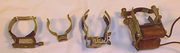
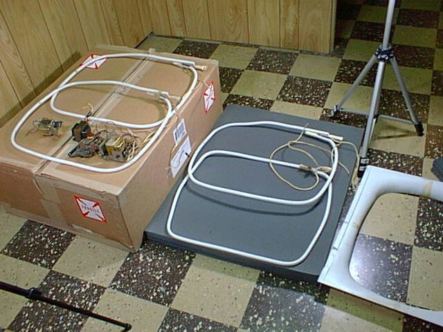
From left to right are an adjustable ion trap (somewhat rare), a standard trap, a 4 pole trap (rare), and a 4 pole electromagnetic trap (very rare).
Adjustment of the trap was simple - move it around until the picture is at it's brightest.
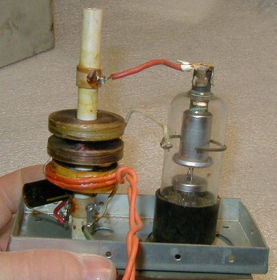
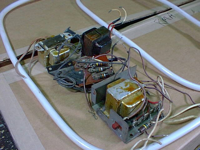
The primary coil is on the bottom, with the orange rectifier filament winding on the outside. The primary would be driven by a 6V6, 25L6 or even a 6C4 tube. The wire ring around the rectifier provided feedback to the driver tube to keep it oscillating.
The secondary coils are the upper two packs (sometimes called pi's), which step the voltage up to 6KV.
The rectifier filament was powered from the 2 turns of orange wire. It was very dangerous to measure the filament voltage, so it was always recommended to compare the brightness of the rectifier filament to the brightness of another tube which was heated with a flashlight battery. Good idea.
I later used this transformer in another HV oscillator project, which can be seen in another photo later on. The white wire on the right was the feedback to the oscillator tube, a 6V6 in this case.
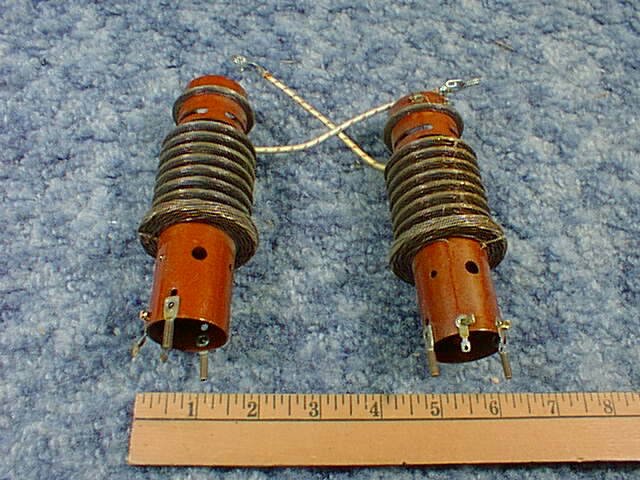
These are the fluorescent tubes which provide the light. They are fed about 1200V from a transformer.