Motorola 7 inch TV
Motorola?
Ever wonder where those names come from? In this case, a small company was formed to produce car radios. At the time, the "ola" stuck on the end of a brand name was really cool. There was Victrola and Radiola, so a radio on a motor car should be called a Motor Ola.
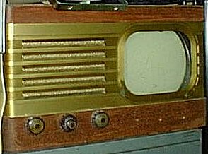
I still remember seeing the Motorola TV that dad bought long before I was around. This set is just like it, except for a darker finish and it's missing the Motorola escutcheon. It was the third Television in the area, so we had LOTS of company over to gather around that 7 inch screen. Notice the use of the more modern term "television", as opposed to the earlier term "televisor".
Unfortuantely, dad had to gave up fixing it so often, and I got to it before I realized what it was worth. Sets like this usually need to have all the paper capacitors (condensers) replaced, especially the high voltage deflection couplers.
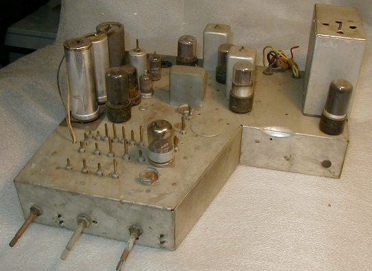
The rest of these photos are of another Motorola chassis of the same model.
This is the front of the chassis. Some of the tubes are missing, but the locktal tube in the front end is still there. The adjustment shafts in the front center are all of the tuner adjustments. The set had about 6 channel positions, so it was necessary to tune the antenna, RF, and oscillator coils for each local channel when the set was installed. That was enough work in itself, but this set was shipped with the chassis, cabinet, and all the tubes separate. A technician had to come out to the house to plug in all the tubes, align the tuner, and put it in the cabinet.
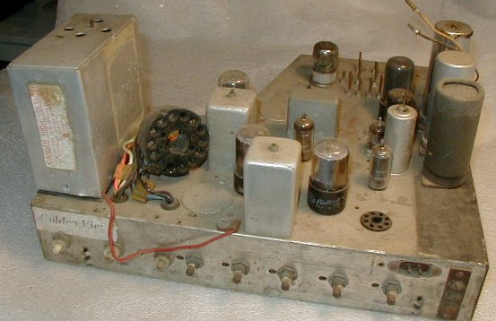
Here's the rear of the chassis, showing the 14 pin CRT connector. The base of the picture tube was almost as big as the screen. A picture of the 7JP4 CRT can be seen under the Tubes section. The three rear panel pots have plastic shafts - they are operating at 6KV, so lots of isolation is needed. Inside the box is the HV oscillator coil. A picture of the coil can be seen in the TP Parts section.
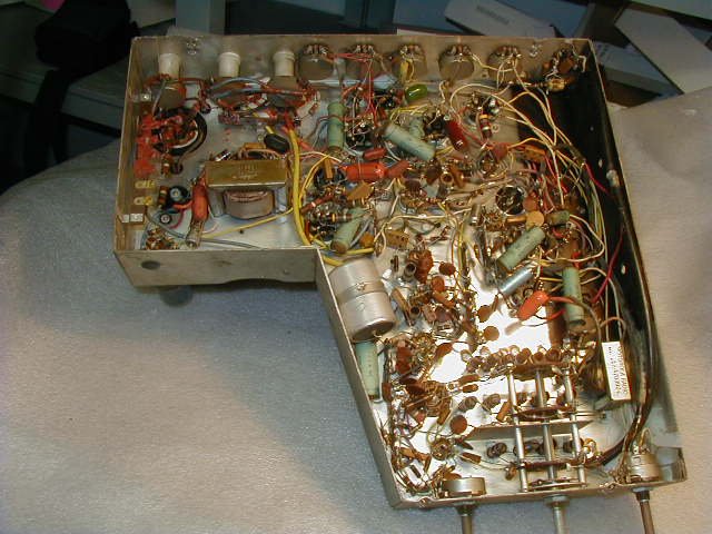
Here's the bottom of the chassis. The HV circuitry is in the upper left. The open spaces are where the HV coupling caps go. The large aluminum cylinder near the center of the picture is the main HV filter. As you can see, a lot of parts have been replaced, and a lot more of the blue paper caps still need to go. I prefer to use the mylar caps, usually in the orange or green packages. The power supply is in the upper right corner. The empty space there is where the old selenium rectifiers were. They were replaced by a pair of 1N4004 diodes.
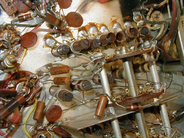
This is a closeup of the tuner section. The high band coils are to the left - they have the fewest turns. This particular chassis has been retuned many times as can be seen by the chewed-up ferrite slugs.
Looking at pictures like this remind me of the power of digital photography. Back then, I had to sketch out wiring like this before replacing any parts. Nowdays, it's easier to just take a picture (no developing) and know exactly where everything was originally.
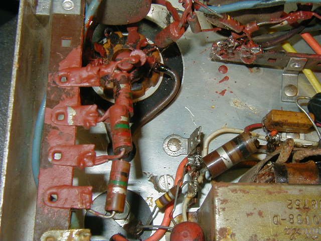
Here's the high voltage section. The red stuff is insulating glypt. Some people use it to seal adjustment screws, but this is what it's supposed to be used for. When Motorola started making 14 inch tv's, they still put all of the HV circuitry under the chassis, and used a LOT of glypt.
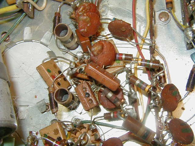
Here's the IF section. Not much to it. At the left side is the botton of a "blunder button", normally used to correct the problem of having an unwanted hole..........
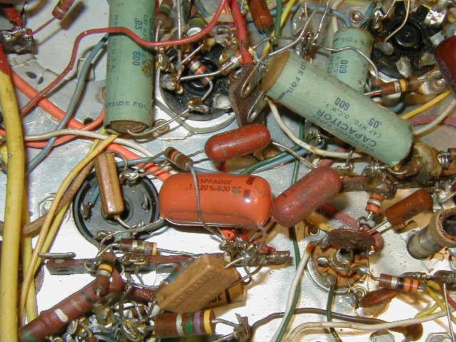
This is the video detector and sync section. Pretty much standard, but old fashioned point-to-point wiring is so nostalgic.
Museum page