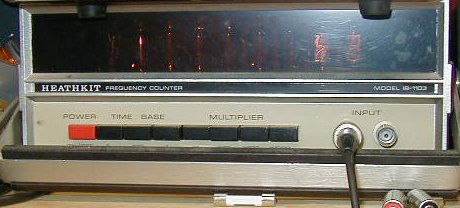
This one is supposed to go to 180 MHZ. It goes past 220.
It also has a multiplier so you can get .001 HZ resolution readings with the 1 second time base.
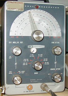
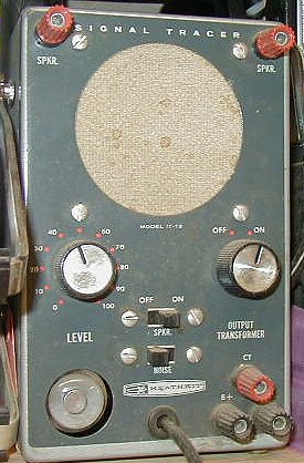
The idea here is to replace each tube section with a FET, and lower the plate resistors. The pilot light will no longer work, but the current drain is so low that even an LED would draw more than the generator. One 9V battery has lasted me years.
You will need 4 N-FETs. I used Motorola HEP F0015. Pin 1 is Drain, pin 2 is Source, pin 3 is Gate.
You will also need a 100 ohm resistor, a 75 ohm resistor, a 9 volt battery, and a battery snap.
Start by pulling the tubes, then remove the line cord.
Solder the FETs to the pins on the tube sockets as follows...
FET 1
lead 1 to 12AT7 pin 6
lead 2 to 12AT7 pin 8
lead 3 to 12AT7 pin 7
FET 2
lead 1 to 12AT7 pin 1
lead 2 to 12AT7 pin 3
lead 3 to 12AT7 pin 2
FET 3
lead 1 to 6AN8 pin 6
lead 2 to 6AN8 pin 9
lead 3 to 6AN8 pin 8
FET 4
lead 1 to 6AN8 pin 1
lead 2 to 6AN8 pin 3
lead 3 to 6AN8 pin 2
Solder the 100 ohm resistor across the 4.7K resistor at 6AN8 pin 1
Solder the 75 ohm resistor across the 33K resistor between the back deck of the band switch, and the B+ point on the bottom
terminal strip.
Wire the battery snap negative lead to ground.
Wire the battery snap positive lead to one side of the power switch.
Wire the other side of the power switch to the end of R17 (2200 ohm 1W) which is not connected to the B+ rectifier. The
existing filter cap will work fine. Since the power switch is connected to the B+, the line cord must be removed.
I did not have to readjust any of the coils as I recall. My generator has a small trimmer cap for fine frequency adjustment.
Hopefully, your modification will also work fine.
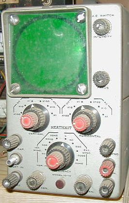
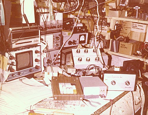
Starting on the left, bottom to top:
Heath IO4550 scope and Heath IB1103 counter.
8038 function generator, capacitance meter, tracking power supply.
30 MHZ counter, variable power supply, (Panasonic cassette player), audible continuity tester.
Hex keypad, 5/12V supply.
The box with the 6 knobs is a resistance substitution bax, and the one with the 2 knobs is a capacitor substitution box.